Design Files & Key Components
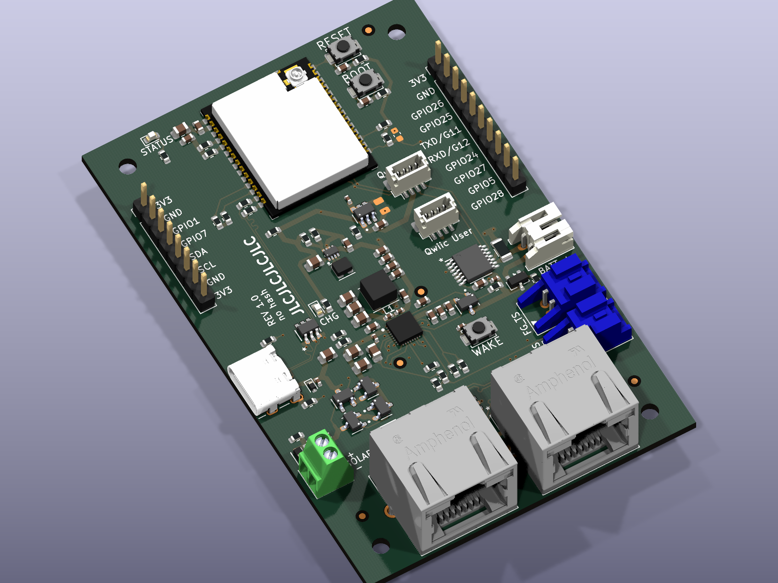
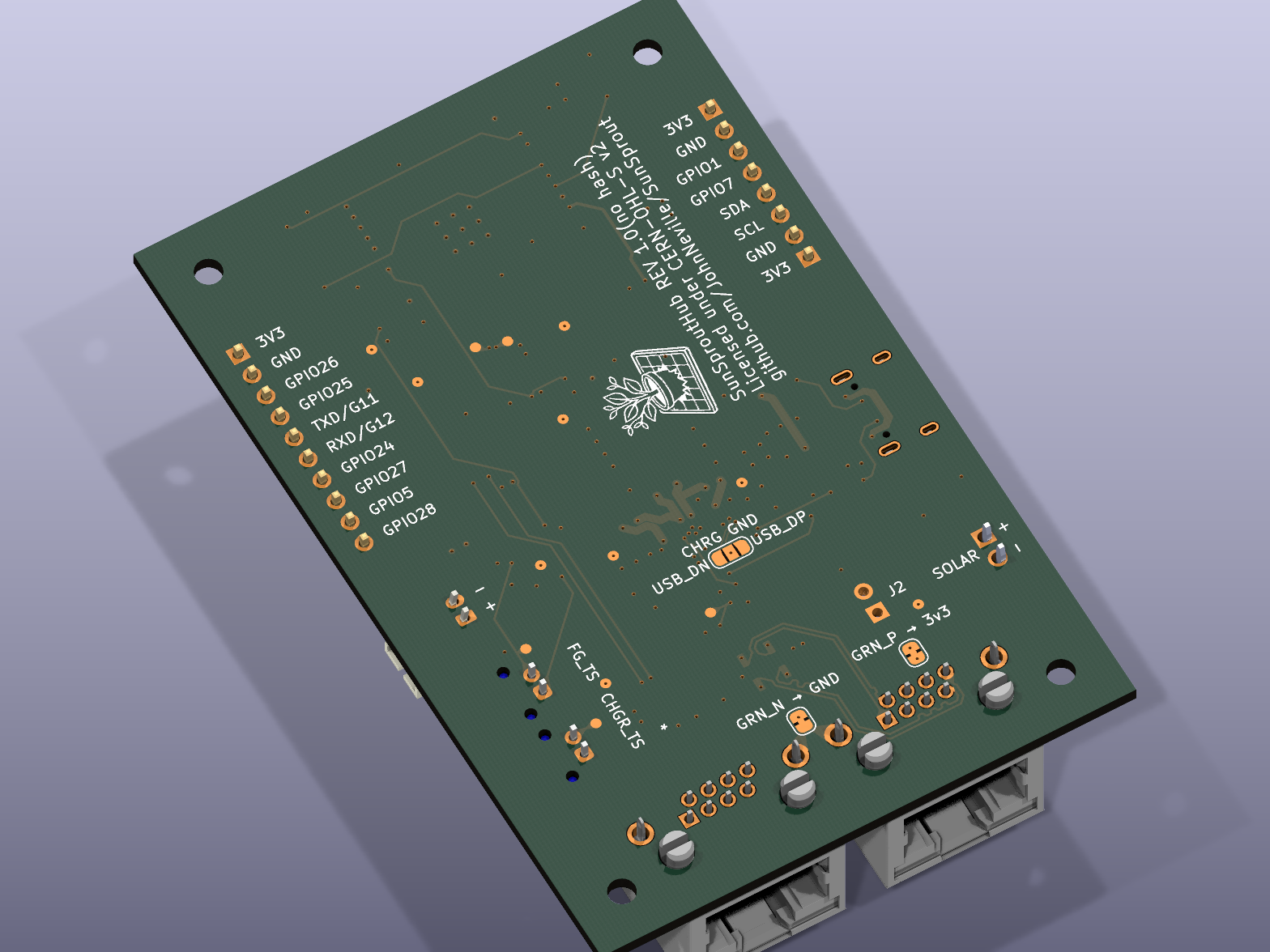
Key components
| Ref | Part | Function |
|---|---|---|
| U1 | ESP32-C5-WROOM-1U | Main MCU, Wi-Fi 6 / Bluetooth 5 / 802.15.4 / CAN FD radio module |
| U8 | BQ25798 | Li-ion/Li-Po battery charger |
| U3 | BQ34Z100 | Fuel gauge |
| U4 | TPS631000 | Buck-boost regulator, 3.3V system rail |
| U5 | TPS22918 | Load switch, switched 3.3V user rail |
| U201 | PCA9615 | Differential I2C buffer, drives the two 8P8C jacks |
| D5, U202 | USBLC6-4SC6-ES | USB-C and I2C-buffer ESD protection |
| Q1, Q2, D2 | MDD3415, DMP3098L-7, BZT52C12S | Reverse-polarity protection on the battery and DC/solar inputs; D2 clamps Q2's gate |
For why each of these parts was chosen, and why its surrounding passives have the values they
do, see the per-IC design notes in the repository's docs/hub/modules/ folder.
A note on the BOM
The bill of materials is optimised for small-batch assembly, not for volume production.
Assembly houses charge a one-off setup fee per distinct part number on top of each component's per-unit price. On a run of tens of boards, that setup cost dominates — so this design deliberately fits a higher-specified part where a cheaper one would do, whenever that part is already used elsewhere on the board. All the 4.7 µF positions share one 25 V 0805 part, for instance, even where 6.3 V would be sufficient.
That yields 61 distinct part numbers across 112 placements. If you intend to build this at volume, revisit those choices: once per-unit cost dominates, fitting the cheapest adequate part in each position is the cheaper answer. Nothing electrical depends on it.
Downloads
Published with the site:
- Hub Schematic (PDF) — all sheets, regenerated
directly from the
.kicad_schsource. - Hub Interactive BOM — hover any reference designator to highlight it on the board.
- Satellite Schematic (PDF) — multi-sheet schematic for the Satellite board.
- Satellite Interactive BOM — interactive pinout and BOM viewer for the Satellite board.
Published per release, on the Releases page:
- 3D model (STEP) — board mechanical model, including the MCU module. Every part carries a 3D model, embedded in the board file itself, so the export is complete.
- Gerbers, BOM, and pick-and-place — the JLCPCB-format fabrication set.
The STEP model is about 19 MB and changes with every layout edit, so it ships as a release asset rather than living in the repository, where each regeneration would add another copy to the history permanently.
Everything above is a build artifact of the KiCad source. Regenerate the site assets with
tools/generate-docs-assets.sh; Docker is the only prerequisite there, and no local KiCad
install is needed. The fabrication set is built by the Release artifacts workflow, which can
be run from the Actions tab against any commit without tagging one.